
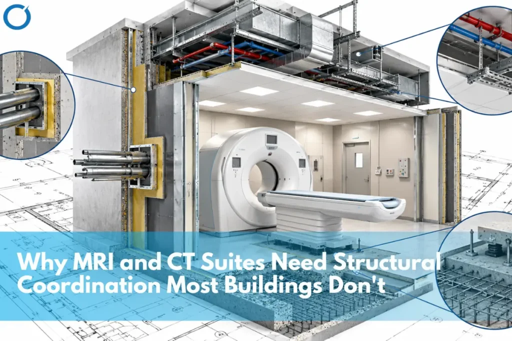
Most hospital floors accommodate people and ordinary equipment. MRI rooms must accommodate a magnet, while CT rooms must accommodate a radiation source. Both require special design considerations that depend on information from outside the core design team, including the equipment vendor’s loading requirements, the shielding supplier’s system details, and the medical physicist’s shielding design. If the structural designer receives this information after completing the design, the project team has only one option left: rework.
MR imaging suite coordination structurally involves aligning the structure of the building with demands external to the designer’s control, namely the magnet supplier’s loading schedule, a separate design of RF and magnetic shielding, and a design by a medical physicist. In the case of MR, this involves the loading demands of the magnet, the use of a depressed slab, a six-sided RF shield, non-ferrous hangers and piping near the magnet, and a quench vent. In CT, it involves radiation shielding, the type of slab, and wall penetrations.
| Concern | Ordinary Clinical Space | MRI Suite | CT Suite |
|---|---|---|---|
| Floor load | Standard occupancy loading | Concentrated magnet foot loads from the manufacturer’s loading diagram | Gantry and table, roughly 4,000 to 8,000 lb on a small footprint |
| Shielding | None | Complete six-sided RF enclosure, plus steel plates where the magnetic field escapes | Lead or concrete barriers designed by a qualified medical physicist |
| Material limits | None | Non-ferromagnetic hangers and piping within the 5-gauss line | Penetrations through shielded walls may need baffling with supplementary lead |
| Vibration | Rarely a design driver | Early vibration test; slab may need isolation | Sensitive to nearby heavy equipment and traffic |
| Special routing | Standard MEP | Dedicated quench vent pipe to the building exterior | Rigging path through doors, halls, and elevators |
Where the Constraints Come From
For a regular structure, the architect, structural engineer, and MEP engineer would coordinate with one another through Structural BIM Services. For these suites, however, a third set of criteria comes into play from experts who do not coordinate within the group:
- The equipment vendor. The loading diagram by the manufacturer pinpoints exactly the locations and magnitude of loads on each magnet foot, and it is up to the structural engineer to design for this.
- The shielding supplier. One contractor often supplies magnetic/RF shielding in a delegated design and hence falls outside the core set of designs.
- The medical physicist. A physicist determines the location and thickness of magnetic shielding plates, while a qualified expert must design CT shielding in accordance with NCRP Report 147.
A delegating design is one whereby the manufacturer of the shielding does the engineering of the shielding, while the design engineers have to integrate it within the building structure. The planning guidelines are quite uniform in regard to timing. The ETS-Lindgren MRI planning guideline recommends starting magnetic field planning as soon as the project team selects the MRI equipment. NCRP 147 also recommends that the shielding specialist, architect, and structural engineer discuss how the floor system interacts with the shielding.
MRI: What the Structure Has to Carry and Avoid
The 5-Gauss line marks the point where pacemakers and other implanted devices could fail, and having that within the designated control area is one of the main objectives when planning for an MRI location. Many of the structural considerations revolve around that single line:
- Concentrated magnet load. The weight of the magnet ranges between 9,000 and 20,000 pounds, and the route into the building through the doorway width, corridor turns, lift capabilities, and knockout walls is as important as the size of the slab.
- A complete RF enclosure. The shield should be continuous on all six sides, and the doors and windows should offer RF shielding as well. The box itself is adding additional weight to the structure.
- A depressed slab. The floors are usually set back by around one to one-and-a-half inches to accommodate the RF floor system and to have flush finishes at the doorway; therefore, the floor depressions, underground conduits, and trenches must be coordinated.
- Magnetic shielding where the wire comes out. Steel plates in the floor, wall, or ceiling will pull the magnetic field back into the room. Vertical shielding, which involves floors above and below, is the least considered aspect.
- Non-ferromagnetic materials nearby. The hangers within the 5-gauss line will usually be aluminum or stainless steel, while the sprinkler piping is usually made of brass or copper.
- A tight ceiling plenum. MEP BIM Services help coordinate ductwork, lighting, cabling, and the quench vent between the architectural ceiling and the RF shield ceiling.
- Vibration. It is recommended that the vibration and electromagnetic interference survey be done even before the completion of the site to determine whether the slab should have a vibration pad.
- A quench vent. A separate pipe from the magnet to the exterior of the building should be routed in the most direct way possible, and this pipe should run across the RF enclosure without piercing the shield.
- Grounding and bonding. There are potential difference problems that may occur when there is a difference in electrical noise. This problem can be solved by the coordination of the bonding paths and the electrical and structural designs.
- HVAC through the shield. The ductwork cannot simply pass through the RF enclosure, but waveguides and filters are required for the airflow.
Layout is often the cheaper lever. The plan provided by ETS-Lindgren states that layout changes should be considered before implementing magnetic shielding, and this is a structural coordination as much as it is a clinical one since relocation of either the magnet or the control room alters which levels/areas will be affected by the field.
CT: Shielding Mass and Slab Choices
CT does not use a magnet, so teams can usually plan rigging more easily. However, the radiation shielding directly affects the structure. Designers cannot treat the slab, walls, or duct penetrations as neutral building elements because each one can influence the shielding requirements.
- Lead or concrete barriers. One-sixteenth of an inch of lead is the equivalent of 4 to 6 inches of standard-density concrete, and high-workload spaces adjacent to occupied areas may require even more.
- Slab type matters. Lightweight concrete may be used in floors to save on weight and provide fire protection, but it is less dense and offers less shielding than standard concrete, requiring careful consideration of floor and ceiling shielding.
- Penetrations. Openings through shielded walls may need baffling with supplementary lead, so duct and conduit locations affect the shielding design.
- Gantry load and vibration. CT is sensitive to vibration, and the equipment is quite heavy for its size, which explains why the ground floor is typically chosen by default.
- Doors, windows, and interlocks. Lead-lined doors, lead glass observation windows, and door interlocks form part of the shielding design, and as such, will need to be sorted out along with the construction of walls.
- Adjacent occupancy. Shielding is dependent on the nature of the surrounding spaces; changes to the use of a neighboring room could very well alter the shielding requirements of the wall.
Why This Becomes Rework
None of these constraints is hidden. They come in from different factions at different times. If the team prepares the slab before receiving the load diagram, hangs the ceiling from standard steel supports, or creates wall openings before the physicist completes the analysis, the project may require the same structural work twice. For an operating hospital, Healthcare Preconstruction Services also need to account for the infection control risk assessment before demolition or slab work begins.
What a Coordinated Model Checks
Coordination gives the structural engineer, architect, MEP consultant, and external specialists a chance to compare these constraints before the team pours slabs or orders shielding. Through clash detection services, that means checking:
- Magnet foot loads and slab depressions against the structural design
- RF enclosure penetrations, including the quench vent, waveguides, and conduit, against each other and the shield boundary
- The non-ferromagnetic hanger and piping areas within 5-gauss zone
- The lead-lined walls, doors, and windows in relation to duct and conduit penetrations
- Delivery path width, turns, and knockout walls for the equipment
- Grounding and bonding paths for the RF shield
- Slab and wall material designations against the physicist’s shielding assumptions
The shielding design itself still comes from the physicist and the shielding supplier. This is where BIM coordination in construction helps ensure that every discipline fits around these requirements and gives the owner a clear record of what the team has confirmed before ordering shielding or pouring the slabs.
Coordinating an MRI or CT Suite?
Optimar Precon coordinates vendor loading diagrams, shielding details, and structural design in one model before pouring slabs or ordering shielding. Contact us for more information about your project.
FAQs
No. RF shielding is necessary for current MRI imaging machines; magnetic shielding is necessary when the 5-gauss line will otherwise run into uncontrolled space. Reconfiguration of the floor plan is usually considered before installing steel plate.
It can, but the floor may need reinforcement to support the magnet’s concentrated load, and the design may also require vibration isolation. The team must also check magnetic field containment for the floors above and below.
A strong magnet makes ferromagnetic materials within the 5-gauss line a safety concern. Teams therefore typically use non-ferromagnetic materials in this area, such as aluminum or stainless steel for hangers and brass or copper for piping.
The qualified medical physicist designs it, based on NCRP Report 147 and taking into account the workload and adjacent occupancy. Then the architect and structural engineer coordinate floor systems and penetrations around this design.
Concrete helps with shielding; moreover, lightweight concrete is not as dense as standard concrete, which means that slabs selected for weight or fire resistance can lower shielding capabilities.