
- Where Zone Valve Coordination Actually Breaks Down
- The Renovation-Specific Trap: Legacy Outlets Without Zone Valves
- Height and Wall Coordination: What 2D Drawings Miss
- What Happens When the Authority Having Jurisdiction Disagrees
- NFPA 99 Requirement vs. Coordination Risk
- Documentation That Has to Match the Installed System
- What to Confirm With Your Design Team Before Precon Starts
- FAQs
A zone valve installed in the wrong place under NFPA 99 doesn’t fail quietly. It fails in front of an inspector, after the wall is closed, and moving it means cutting back into finished construction. Five specific placement rules govern where these valves can go:
- A wall must intervene between the zone valve and every outlet it controls.
- The zone valve serves only outlets on the same story; it cannot control gas lines on a different floor.
- The valve cannot sit in the same room as the outlets it controls, even if a wall technically intervenes.
- Every Category 1 space and every anesthetizing location needs its own dedicated zone valve, located immediately outside the room.
- The valve must be operable from a standing position, which sets a specific mounting height regardless of what else is on that wall.
None of these rules is complicated alone. The trouble starts when all five apply to one real wall that also has a window, a door swing, and someone else’s conduit run planned for the same few square feet.
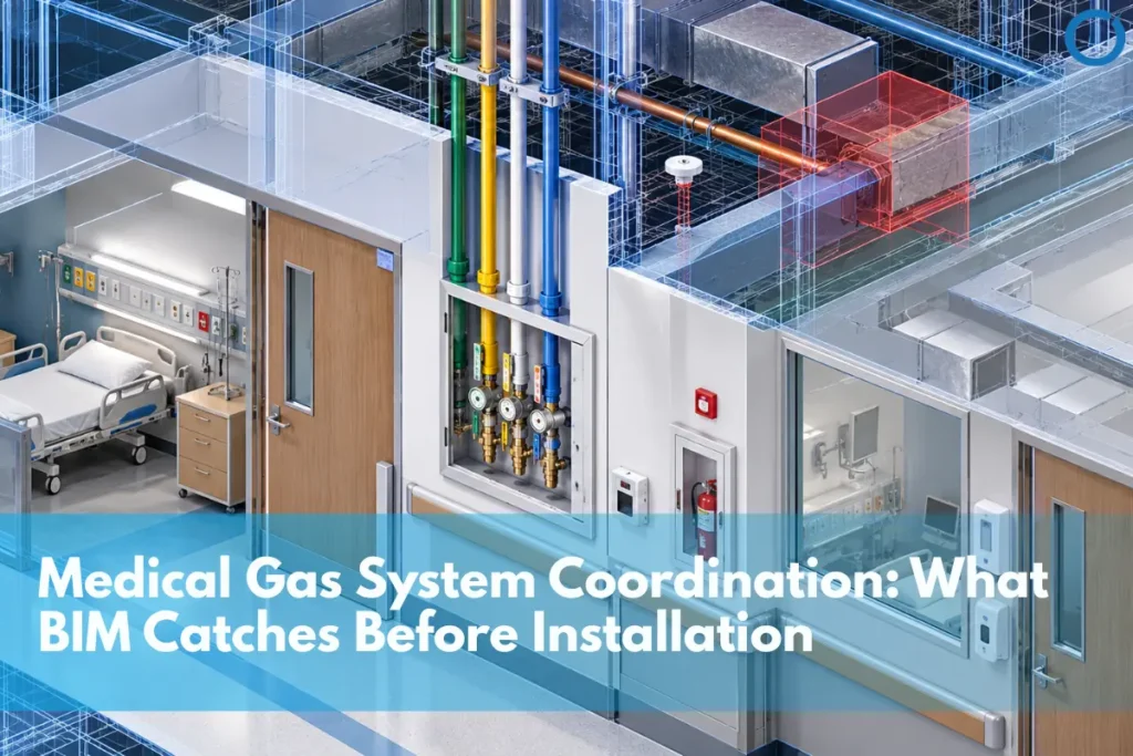
Medical gas system coordination through BIM catches zone valve placement conflicts, wall-intervening violations, same-room placement, and height conflicts with windows or other wall-mounted equipment before installation, when a model change costs nothing and a field correction means reopening finished walls. It also catches the renovation-specific problem of legacy outlets that were never piped through a zone valve box at all, which NFPA 99 now requires to be corrected whenever that area is renovated. Coordinating this system early, in the same clash detection pass as electrical and structural systems, is what keeps a hospital project from failing a life safety inspection after substantial completion.
Where Zone Valve Coordination Actually Breaks Down
The most common failure isn’t a designer ignoring the code; it’s the code’s requirements colliding with something else on the same wall that nobody flagged as a conflict until both were already built. A zone valve box needs a specific height for standing-position operability, and that height frequently lands in the same zone as a window sill, a fire extinguisher cabinet, or a nurse call station that another discipline placed independently.
- A zone valve modeled at standard mounting height conflicts with a window head height set by the architectural team working from a separate elevation.
- A valve box placed correctly on paper turns out to share a wall cavity with structural blocking or electrical rough-in that was routed without knowing the valve box needed that space.
- A valve serving a Category 1 space gets placed inside the room it controls because the corridor-side wall didn’t have room in the 2D drawing set, a violation that’s easy to miss without 3D spatial validation.
- Two disciplines both claim the same corridor wall segment: the medical gas trade for a zone valve box, another trade for a panel or cabinet, with neither aware of the other’s plan until installation. This is where BIM Coordination Services help teams review architectural, structural, and MEP interfaces together before installation begins.
- A valve is modeled correctly for the current floor plan, but a late architectural revision shifts the room boundary, silently invalidating the same-room and wall-intervening checks that were verified against an earlier layout.
The Renovation-Specific Trap: Legacy Outlets Without Zone Valves
Hospital renovation work carries a coordination risk that new construction does not: existing medical gas outlets may date back to older code editions that predate current zone valve requirements. NFPA 99 now requires project teams to connect any medical gas outlet in a renovated area to a compliant zone valve box if the existing system does not already provide one. As a result, a renovation that appears to affect only a small area can expand into a much larger piping and valve retrofit once the team surveys the existing system against current code requirements.
- Record drawings often don’t reflect reality; outlets added in past field changes may never have made it back onto the official drawing set.
- A verified existing-condition survey, supported by Point Cloud to BIM Services, can help confirm which outlets and systems actually exist before renovation design begins.
- Scope discovered mid-project costs more than scope priced upfront; a retrofit found during commissioning competes with an already-locked schedule and budget.
This is where As-Built BIM Services matter as much as the new design. A precon team working from outdated record drawings instead of a verified as-built condition can miss exactly which existing outlets lack a compliant zone valve, and that gap surfaces during commissioning rather than during estimating at the point where it’s most expensive to fix.
Height and Wall Coordination: What 2D Drawings Miss
Two-dimensional drawings show a zone valve as a symbol on a wall, without the vertical dimension that actually determines whether the placement works. A coordinated 3D model changes that:
This type of multidisciplinary review forms part of the broader BIM coordination process, where teams combine architectural, structural, and MEP information before construction.
- Check the mounting height against every other wall-mounted element on the same wall, including windows, casework, and fire safety equipment, rather than reviewing it only against the floor plan.
- Confirm that the wall cavity has enough space before structural blocking or other MEP rough-in claims the same location.
- The room-boundary rule is verified geometrically; the model can confirm a zone valve genuinely sits outside the space it controls, rather than relying on a 2D symbol that doesn’t capture which side of a wall assembly the valve actually falls on.
What Happens When the Authority Having Jurisdiction Disagrees
Zone valve rules read as straightforward on paper, but they leave real room for interpretation in practice. MEP BIM Services help teams coordinate medical gas valve locations with architectural, structural, electrical, and mechanical elements before those placement decisions reach the inspection stage.
- If the verifier or Authority Having Jurisdiction rejects a valve location, the project team may need to relocate the valve, even if the design team interpreted the code differently.
- Good practice often goes beyond the code minimum. For example, placing a zone valve along a natural egress path may not be mandatory, but it can improve staff access during an emergency shutoff.
- Zoning decisions should group spaces logically for emergency shutoff, not just satisfy the letter of the placement rules room by room.
Coordinating to the code minimum alone still leaves a project exposed to a verifier’s judgment call on inspection day. Modeling against both the hard rules and their intent is what actually reduces that risk.
NFPA 99 Requirement vs. Coordination Risk
| Requirement | What It Means | Precon Impact |
|---|---|---|
| On-site generation matching MIC | Dispatchable capacity equal to 100% of requested import capacity | New electrical scope distinct from redundancy-driven backup power |
| 80% additional renewable requirement | New Irish renewable generation covering most annual demand | Requires a credible delivery plan documented before application |
| Separate connection for generation asset | On-site or proximate generation requires its own grid connection | Additional application process and metering scope |
| Capacity-based routing | Under 20 MVA to ESB Networks; 20 MVA+ to EirGrid | Determines which System Operator process and timeline applies |
Documentation That Has to Match the Installed System
NFPA 99 requires facilities to maintain zone valve diagrams showing exactly which outlets each valve controls, along with specific labeling requirements at the point of installation:
- Every outlet and inlet must be labeled with the gas name.
- Both sides of every zone valve box must identify the gas type and the specific area that valve controls.
- The facility must keep zone valve diagrams current and maintain an accurate record of which outlets each valve serves, rather than relying on documents that reflect only the original design intent.
A model-derived set of these diagrams stays accurate through construction changes in a way a diagram drafted once at design intent doesn’t, which matters directly for the kind of clash detection process that should be catching these placement conflicts in the first place, since the documentation and the coordinated model need to agree with each other, not just with the original design.
Coordinating Medical Gas Systems for a Healthcare Project?
Optimar Precon provides Healthcare Preconstruction Services that coordinate medical gas zone valve placement alongside electrical, structural, and mechanical systems, checking layouts against NFPA 99 placement requirements before installation rather than after an inspection fails. Contact us to discuss your project scope.
What to Confirm With Your Design Team Before Precon Starts
- Confirm which code edition applies. NFPA 99 section numbers for zone valve placement have shifted slightly between editions, and the applicable edition depends on jurisdiction and permit date.
- Request a verified as-built survey for any renovation scope, not just the original record drawings, before pricing zone valve retrofit work.
- Check zone valve height requirements against every other wall-mounted element in the same location instead of reviewing the medical gas system in isolation.
- Ask whether the team will generate zone valve diagrams directly from the coordinated model or draft them separately. Separately maintained diagrams often fall out of sync with field conditions first.
FAQs
No, NFPA 99 specifically prohibits a zone valve from being located in the same room as the outlets it controls, even where a wall or partition might otherwise seem to satisfy the intervening-wall requirement.
Every Category 1 space and every anesthetizing location needs a dedicated zone valve located immediately outside it. The specific grouping of rooms under one valve versus separate valves depends on how the spaces are classified and organized, not a blanket one-valve-per-room rule.
Renovation work can uncover legacy outlets that predate current zone valve requirements. NFPA 99 requires project teams to correct these conditions during the renovation, which can expand the scope if they do not verify existing conditions through an as-built survey.
A model-stage correction is a design change with no construction cost attached. A conflict caught during inspection typically means reopening finished walls, relocating piping and the valve box, and rescheduling the inspection a categorically more expensive and disruptive fix.
Facilities must keep current zone valve diagrams that show which outlets each valve controls. Any field change to valve assignments requires an update to the documentation as well as the as-built model.