- Why This Readiness Gap Exists
- What High-Density Cooling Adds to a BIM Model
- Where Traditional BIM Practices Fall Short
- New Clash Categories That Didn't Exist in Air-Cooled Designs
- Air-Cooled vs. High-Density/Liquid-Cooled: What Changes in the Model
- A Readiness Checklist: Is Your BIM Practice Ready?
- How to Close the Readiness Gap Before the Project Starts
- Modeling Readiness Is a Prerequisite, Not an Afterthought
- FAQs
While your BIM model was designed specifically for a traditional air-cooled data center, it does not necessarily apply to a high-density, liquid-cooled data center, which requires new equipment, clashes, and coordination issues that would never have appeared with air cooling. A high-density cooling BIM model is not about designing systems you already know how to do, but about systems you’ve never worked with before.
It is no rhetorical question posed in the title. Almost all BIM teams working with data centers have developed their libraries of components, coordination checklists, and clash detection processes based on air-cooled equipment, since that is what most data center projects required until quite recently. A team can be truly skilled in air-cooled MEP coordination and yet unprepared for a liquid-cooled project due to the nature of the information the model requires.
Why This Readiness Gap Exists
Teams build component libraries, coordination templates, and clash detection rule sets incrementally from their previous modeling experience. For example, a company that has coordinated many air-cooled data center projects may have a strong library of CRAC units, ductwork, and containment systems but no models for CDUs, manifolds, or leak detection zones. The team would not need those components until it begins work on a liquid-cooled data center project. This is not a skills gap because the team is less capable; it is a content gap in the model and process of coordination.
A BIM model is ready for high-density cooling only when it includes CDUs, manifolds, quick-disconnect fittings, leakage zones, chillers and CRAC units. Teams must also coordinate cooling pipes with electrical systems, structural elements and cable trays. A model limited to LOD 300 ductwork and conventional air-side equipment cannot support the coordination needs of a liquid-cooled or high-density cooling system.
What High-Density Cooling Adds to a BIM Model
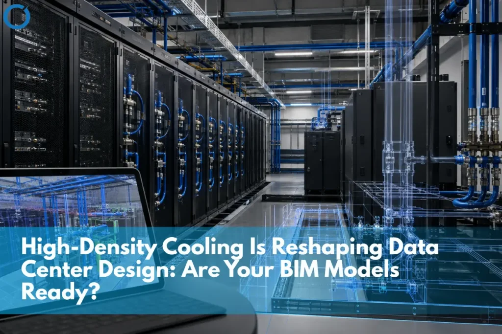
Air-cooled data center models are built around a well-established set of elements: CRAC/CRAH units, ductwork, and hot/cold aisle containment. Liquid cooling introduces equipment that many air-cooling-era models were never built to represent: coolant distribution units (CDUs) that manage fluid flow to the racks, manifolds distributing coolant to individual servers, quick-disconnect fittings at each rack connection, and leak detection sensors monitoring the piping runs. None of these have a direct equivalent in an air-cooled model, which means adding them isn’t a matter of relabeling existing families; it’s new content the model has to account for from scratch.
Each of these elements also introduces its own coordination dependency. CDUs need floor space, structural support, and often a dedicated mechanical room allocation that an air-cooled layout wouldn’t have planned for. Manifolds and piping runs need routing paths that don’t conflict with the cable trays and conduit already competing for the same raised floor plenum. Quick-disconnect fittings at the rack level need clearance for maintenance access, which changes rack spacing assumptions that were set based on airflow requirements alone in an air-cooled design. None of this is exotic engineering; it’s straightforward modeling work, provided the team knows to include it and has done it before.
Where Traditional BIM Practices Fall Short
Most data center MEP BIM services use LOD 300 or LOD 400 models for standard mechanical, electrical, and plumbing coordination. However, liquid cooling requires teams to model piping routes, CDU locations, connections, containment zones, supports, and maintenance clearances with greater precision. A model that hasn’t been scoped for liquid cooling from the outset often treats these elements as an afterthought layered on top of an already-coordinated air-cooling design, rather than a system that needs to be coordinated alongside everything else from the start.
This readiness problem reflects several common challenges in MEP BIM modeling, including insufficient LOD, incomplete component libraries, siloed discipline models, and clash rules that do not cover project-specific equipment.
New Clash Categories That Didn’t Exist in Air-Cooled Designs
- Piping-to-electrical conflicts — coolant piping now competes for the same routing space as electrical conduit and cable tray in ways air ducting never did.
- Piping-to-structural conflicts — CDU placement and manifold locations need structural support consideration that standard air-cooling equipment didn’t require.
- Leak containment zones — liquid cooling introduces a spatial requirement (containment and drainage paths) with no equivalent in an air-cooled design.
- Teams must expand their clash detection services beyond standard ductwork checks to include coolant piping, structural supports, cable trays, electrical routes, access clearances, and leak-containment zones.
- Rack-level connection points — quick-disconnect fittings at each rack need clearance and access modeled individually, not assumed as part of a generic rack footprint.
Our guide explaining clash detection in BIM covers hard clashes, soft clashes, access conflicts, and clearance issues that teams should review within a federated model.
Air-Cooled vs. High-Density/Liquid-Cooled: What Changes in the Model
| Model Element | Air-Cooled Baseline | High-Density / Liquid Cooling Requirement |
|---|---|---|
| Primary cooling equipment | CRAC/CRAH units and ductwork | CDUs, manifolds and coolant piping networks |
| Rack-level detail | Generic rack footprint and airflow clearance | Quick-disconnect fittings and individual connection points |
| New spatial requirements | Hot and cold aisle containment | Leak containment and drainage zones |
| Clash detection scope | Ductwork coordinated with electrical and structural systems | Piping coordinated with electrical systems, structural elements and cable trays |
These additional model requirements demonstrate how teams use BIM in data center construction projects to coordinate dense mechanical, electrical, structural, and cooling infrastructure before installation begins.
A Readiness Checklist: Is Your BIM Practice Ready?
- Does your model library include CDUs, manifolds, and quick-disconnect fittings as modeled elements, or only generic rack and cooling equipment placeholders?
- Does your clash detection process check piping against electrical and structural systems, not just ductwork against those same systems?
- Are leak containment and drainage zones modeled as spatial requirements, or left undocumented until a field issue surfaces?
- Has your team coordinated a liquid-cooled or high-density project before, or will this project require them to model these elements for the first time?
How to Close the Readiness Gap Before the Project Starts
- Build or source component families for CDUs, manifolds, and quick-disconnect fittings before design begins, rather than modeling them ad hoc mid-project.
- Extend clash detection rule sets to include piping-to-electrical and piping-to-structural checks, which most air-cooling-era templates don’t run by default.
- Involve the cooling equipment manufacturer’s specifications early, since CDU and manifold dimensions vary by vendor and affect both structural and clearance requirements.
- Run a dedicated coordination pass for leak containment and drainage as its own review, not folded into general mechanical coordination where it’s easy to overlook.
Not Sure Your BIM Practice Is Ready for High-Density Cooling?
Optimar Precon’s BIM coordination for data centers includes CDU, manifold and piping coordination alongside standard MEP systems. Our teams model liquid-cooling requirements from the start rather than adding them later. Contact us to discuss your project scope.
Modeling Readiness Is a Prerequisite, Not an Afterthought
When teams build a BIM model without considering liquid cooling equipment and clash categories from the start, they coordinate those systems reactively. They often discover conflicts only after finalizing the air-cooled portions of the model instead of coordinating both systems together. Before the project begins, confirm that the team’s model library and clash detection scope include CDUs, manifolds, and piping. This preparation prevents high-density cooling from becoming the last and least coordinated part of the project.
Adding liquid-cooling systems after teams have already coordinated and approved the air-cooled model is one of the broader data center preconstruction mistakes that can trigger redesign, delayed approvals, and repeated coordination work.
The readiness question in this post’s title is worth asking directly and honestly before a bid goes out, not partway through a project when the answer becomes obvious anyway. A team that hasn’t built the component library or extended the clash detection rule set yet isn’t disqualified from the work, but pretending the air-cooled workflow transfers directly, without deliberate preparation, is exactly how liquid cooling coordination becomes the part of the project that falls behind everything else.
FAQs
Teams typically need to model piping, CDU placement, and rack-level connection points at a higher level of detail than standard ductwork. Clash detection in such a dense environment requires precise geometry rather than approximate placement.
The team can use the original air-cooled design as a reference for structural and electrical elements. However, they must design and integrate the cooling-specific components, including the CDU, manifold, piping, and leak containment, from scratch because the original design contains no equivalent systems.
Standard BIM platforms like Revit and Navisworks can model and coordinate these elements, but the team needs component libraries and coordination experience specific to liquid cooling equipment, which not every commercial BIM team has built up yet.
The required effort depends on the team’s existing modeling capacity and the complexity of the selected CDU and manifold equipment. However, teams should make this worthwhile upfront investment before the project begins rather than midway through design, when schedule pressure often encourages shortcuts.
General MEP coordination assumes a known, well-established set of systems: electrical, mechanical, structural. High-density cooling coordination adds equipment types and clash categories that many teams haven’t modeled before, which is a readiness gap distinct from general coordination experience.
Our guide on AI Data Centers Are Changing Power and Cooling Design covers rack density figures, cooling method comparisons, and precon budget implications; specifically, this post focuses on BIM model readiness rather than repeating that ground.