- What Is Scan to BIM?
- How Scan to BIM Works: The Process Step-By-Step
- Scan To BIM vs Traditional Survey Methods
- Level of Accuracy (LOA) Standards: What Tolerance Does Your Project Need?
- When To Use Scan to BIM
- How Much Does Scan to BIM Cost in 2026?
- Scan to BIM Technology and Software in 2026
- Need a Scan to BIM for Your Next Project?
- FAQs
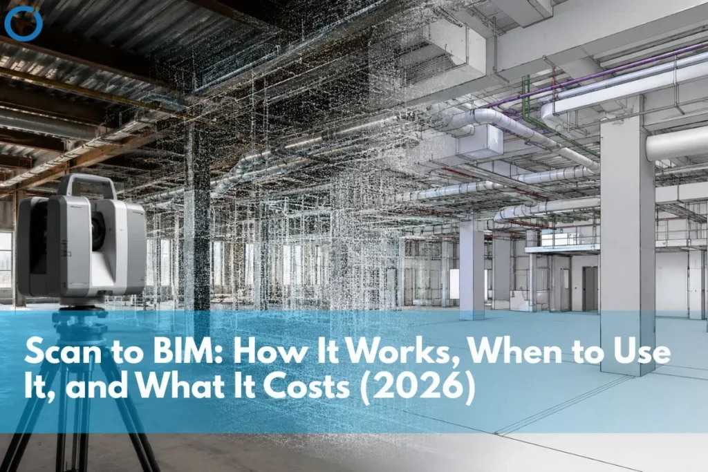
In short, Scan-to-BIM technology involves the use of 3D laser scanning to obtain a detailed point cloud of an existing object or site, which should then be translated into a precise model in the Revit program. In other words, scan-to-BIM allows one to create a true-to-life image of an existing building or site. This method is applied in complex renovation and retrofit projects, heritage works, as well as sophisticated new-build projects, as there is a need for real information about existing circumstances in all cases mentioned above. IndustryARC predicts that the worldwide 3D scanning market will reach the level of over $16 billion by 2030 due to increasing BIM usage within construction. (IndustryARC, 2026)
All buildings and sites are never fully in compliance with the existing drawings. In fact, any building is changed, reconstructed, services are relocated, and other modifications take place, while no alterations are made in documents describing the building. As a result, a designer faces many difficulties as soon as he/she starts a renovation project based on drawings.
Scan to BIM eliminates this problem at the source. The 3D laser scanner makes a precise scan of the building, including all walls, columns, beams, ducts, and pipes, creating a cloud of several million precise coordinate points. Teams then import the point cloud into Revit, where it forms the geometric base of the BIM model with sub-centimeter accuracy.
The following guide will go into detail on the process of scanning to BIM, USIBD Level of Accuracy (LOA) standards for scan accuracy, scanning to BIM versus conventional surveys, when to use scanning to BIM, and cost in 2026.
What Is Scan to BIM?
Scan to BIM, sometimes referred to as Point Cloud to BIM services, is the process of converting data generated by 3D scanning equipment from an existing building or structure into a Building Information Model. This method provides the highest degree of precision compared to traditional survey techniques.
The key distinction is simple: a point cloud captures measured geometry, while a BIM model represents interpreted geometry. Scan to BIM converts real-world conditions into an intelligent, parametric model that project teams can use for design, coordination, clash detection, facility management, and construction documentation.
An error-filled drawing can transfer those mistakes into a BIM model. In contrast, a Scan-to-BIM model uses verified field data, so the model represents the actual conditions of the site or building.
Market context: Market analysts forecast the international 3D scanner market to exceed $16 billion by 2030, with a CAGR of more than 4.5% between 2024 and 2030. In fact, the growth of this market directly correlates with the increased use of BIM modeling on construction sites around the world. Many Scan-to-BIM workflows now incorporate AI and machine learning technologies. (IndustryARC / Fingerlakes1, March 2026)
How Scan to BIM Works: The Process Step-By-Step
Step 1: Site Scanning
Teams position the 3D laser scanner in different locations across the building or site. Terrestrial 3D laser scanners include models such as Leica RTC360, Faro Focus, and Trimble X7. 3D laser scanners emit high-speed light beams and calculate how long each beam takes to reflect after hitting the target surface. This creates many points in three dimensions, hence the creation of a point cloud.
Modern scanners can produce millions of points per second. Scanning a floor in a building only takes hours compared to manual surveying. Teams perform the scans to cover the entire building site, using overlapping fields of view so no elements remain unscanned. This gives project teams reliable site data for Revit Modeling Services.
Step 2: Point Cloud Registration
Software such as Autodesk ReCap, Leica Cyclone, or FARO Scene matches, aligns, and integrates point clouds from each scanner position into one comprehensive point cloud. Registration uses target spheres or natural feature matching to align scans with millimeter precision. The final output is thus a point cloud that integrates all the scanning positions in a single scan.
Step 3: Point Cloud Processing and Quality Check
After registering the point clouds, teams clean the data by removing noise, scanner artefacts, people, vehicles, and other unnecessary elements. They then validate the processed point cloud against the project’s required LOA specifications before using it for Construction Documentation Services, coordination, or model-based review.
Step 4: BIM Modeling From The Point Cloud
Autodesk ReCap then imports the point cloud into Autodesk Revit. The BIM experts generate models of each building component, including walls, floors, ceilings, structure, and mechanical/electrical/plumbing systems, based on the point cloud geometry. This process supports accurate Revit BIM Modeling Services for renovation, retrofit, and existing-condition projects.
The output model consists not only of geometry but also of data and material properties as well as system relations.
Step 5: Quality Assurance and Delivery
Teams evaluate the final model against the point cloud using tools such as ClearEdge3D Verity or CloudCompare, which measure the distance between the cloud and mesh. After verification, the team submits the final model in the required format, such as Revit, IFC, or NWC for Navisworks coordination, along with the point cloud. This verified output supports BIM Coordination Services and downstream clash detection.
Scan To BIM vs Traditional Survey Methods
The decision between scan to BIM and traditional survey methods is primarily a decision about how much downstream risk you are willing to accept. Traditional survey methods are cheaper upfront and produce errors that are expensive to resolve downstream. Scan to BIM is more expensive upfront and eliminates most downstream errors.
| Factor | Scan to BIM | Traditional Survey Methods |
|---|---|---|
| Accuracy | Sub-centimeter accuracy; millions of data points captured per second | Manual measurements prone to human error; typically ±10–20mm tolerance |
| Data capture speed | A building floor can be scanned in hours | Manual survey of the same area takes days or weeks |
| Coverage | Captures all visible geometry simultaneously; no missed elements | Relies on surveyor judgement; elements can be overlooked |
| Complex geometry | Handles irregular surfaces, curved walls, and inaccessible areas accurately | Difficult or impossible to measure complex geometry manually |
| As-built accuracy | Field-verified geometry matched to actual conditions | As-built drawings from memory or partial records frequently contain errors |
| BIM integration | Point cloud imports directly into Revit via Autodesk ReCap model built on verified data | 2D survey drawings redrawn in Revit: errors in drawings propagate into the model |
| Heritage and retrofit projects | Essential captures existing conditions precisely for renovation design | Inadequate historical buildings rarely match original drawings |
| Cost profile | Higher initial cost; significantly lower downstream costs from reduced rework | Lower initial cost; higher downstream costs when survey errors reach construction |
Level of Accuracy (LOA) Standards: What Tolerance Does Your Project Need?
The USIBD Level of Accuracy, or LOA, framework governs Scan to BIM accuracy and sets the industry standard for spatial tolerance in scan-derived documentation. The framework uses standard deviation to define tolerance because measurement always includes a degree of probability. Understanding which LOA your project requires is essential for specifying the right scanning approach and evaluating scan quality.
| LOA Level | Tolerance | Typical Use | BIM LOD Equivalent |
|---|---|---|---|
| LOA 10 | 25mm-50mm | Early concept feasibility, site planning | LOD 100-200 |
| LOA 20 | 15mm-25mm | Design development, general coordination | LOD 200-300 |
| LOA 30 | 5mm-15mm | Detailed design, MEP coordination, clash detection | LOD 300-350 |
| LOA 40 | 1mm-5mm | Fabrication, precision installation, heritage | LOD 350-400 |
| LOA 50 | <1mm | High-precision forensic, structural assessment | LOD 400-500 |
For most commercial renovation and retrofit projects requiring MEP coordination and clash detection, LOA 30 (5-15mm tolerance) is the appropriate specification. LOA 40 is required for precision fabrication work. LOA 20 is sufficient for early feasibility studies.
For a full explanation of BIM LOD levels and how they relate to scan accuracy requirements, see: BIM LOD levels explained.
When To Use Scan to BIM
Renovation and Retrofit Projects
Scan to BIM is most commonly used on renovation and retrofit projects where the existing building conditions need to be accurately documented before design begins. Heritage buildings, commercial refurbishments, building services upgrades, and infrastructure retrofits all benefit significantly from scan-derived As-Built BIM Services.
Complex New-Build Projects with Existing Constraints
New-build projects adjacent to existing structures, on constrained urban sites, or with existing underground services benefit from scan to BIM to capture the existing context accurately. Site boundary walls, neighbouring building faces, underground utility positions, and existing structural elements can all be captured and incorporated into the design BIM model.
Facility Management and Digital Twin Applications
At LOD 500, a scan-derived BIM model becomes the as-built digital record of a completed building, the foundation of a digital twin for facility management, planned maintenance, and future renovation planning. For large commercial, healthcare, and institutional buildings, the LOD 500 model generated from a post-construction scan provides more accurate as-built documentation than drawing-based records.
MEP Coordination on Complex Projects
On projects with dense MEP systems, data centers, hospitals, and industrial facilities, scan-to-BIM provides verified existing conditions data for the coordination model. If both the structural model and the MEP model are generated from scans, then the federated model will be true to reality as opposed to design, because that is important in achieving successful coordination. See more about MEP coordination workflows at: BIM for MEP coordination.
How Much Does Scan to BIM Cost in 2026?
Scan to BIM cost has two components: the scanning cost and the BIM modelling cost. These are often quoted separately, particularly when the client commissions scanning through a survey company and modelling through a BIM specialist.
Scanning Cost
- Small building or single floor (up to 500 m²) – £1,500–4,000 / $2,000–5,000
- Medium commercial building (500–2,000 m²) – £4,000–12,000 / $5,000–15,000
- Large complex (2,000+ m² or multi-storey) – £10,000–40,000+ / $12,000–50,000+
- Heritage or high-complexity projects quoted individually based on access, LOA specification, and scan density
BIM Modelling Cost
BIM modelling from point cloud data is priced per project based on the scope, LOD requirement, and number of disciplines to be modelled. Offshore Revit Modeling Services from point cloud data cost significantly less than equivalent local rates, typically 40–70% below UK and USA market rates, while delivering the same Revit model output.
Cost context: The cost of scan to BIM is consistently offset by the downstream savings from avoided rework and design coordination failures. Projects that proceed without accurate as-built data reliably encounter site conflicts when the design meets the actual building. These conflicts generate change orders, programme delays, and rework costs that exceed the scan to BIM investment on projects of any meaningful complexity.
Scan to BIM Technology and Software in 2026
- Scan equipment – Leica RTC360, FARO Focus Premium, Trimble X7, Matterport Pro3 (for basic purposes)
- Point cloud processing – Autodesk ReCap Pro, Leica Cyclone Register 360, FARO Scene
- BIM modelling software – Autodesk Revit, used for architectural, structural, mechanical, and electrical design through Revit 3D Modeling Services
- Clash detection – Autodesk Navisworks (clash detection in federated models)
- Quality assurance – ClearEdge3D Verity (Cloud-to-Mesh deviation analysis), CloudCompare (open source)
- Emerging tools – AI-assisted modelling tools integrating directly with ReCap and Revit to automate element recognition from point cloud data
Need a Scan to BIM for Your Next Project?
At Optimar Precon, we provide scan to BIM services for architects, engineers, contractors, and developers across the UK and USA, modelling from client-supplied point cloud data in Revit to specified LOD and LOA, with full QA verification. We also provide BIM coordination services and clash detection using the scan-derived model as the coordination base. Get in touch to discuss your project.
FAQs
Scan-to-BIM uses 3D laser scanning to capture the true shape of an existing building or structure. The scan creates a point cloud, and BIM modelers then convert that point cloud into an accurate Revit BIM model. As opposed to using inaccurate drawings, it creates a model based on precise field measurements that represent true existing conditions. This technique is useful in projects like renovations, retrofits, heritage, or any other complicated structures that require existing condition data for design purposes.
Project teams define Scan-to-BIM accuracy using the USIBD LOA system. For commercial renovations and MEP coordination, teams typically use LOA30, which allows a 5–15 mm tolerance. For precise fabrication and heritage projects, teams usually select LOA40, which allows a 1–5 mm tolerance. Nowadays, terrestrial laser scanners are able to operate at sub-centimeter accuracy. After modeling, teams verify accuracy through Cloud-to-Mesh deviation comparison. This process mathematically confirms whether the modeled elements fit the scan data within the required tolerance criteria.
Use Scan to BIM when a project requires highly accurate existing-condition data for design. This includes renovations, retrofits, historic buildings, complex MEP integration within existing facilities, projects with strict tolerances, and projects where teams cannot rely on existing documentation. Manual surveying is suitable only for simple projects that require little to no coordination and do not face serious consequences due to survey inaccuracies during construction.
The workflow uses Autodesk ReCap for point cloud registration, Autodesk Revit for BIM modeling, and Autodesk Navisworks for coordination and clash detection. Project teams commonly use scanning technologies such as Leica RTC360, FARO Focus, and Trimble X7. For verification, teams use ClearEdge3D Verity or CloudCompare to check model accuracy against the point cloud data.
The timeline depends on project size and complexity. Scanning a single building floor typically takes half a day to a full day on site. Point cloud registration and processing takes one to two days. BIM modelling time depends on scope, and a typical single-floor commercial renovation model at LOD 300 takes three to seven working days. A full multi-storey building model at LOD 350 may take two to four weeks. Offshore BIM modelling typically delivers faster turnaround than equivalent local teams.