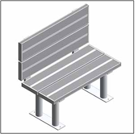
- What Is BIM LOD (Level of Development)?
- BIM LOD Levels At A Glance – Quick Reference Table
- BIM LOD Levels Explained in Detail
- LOD 300 vs LOD 350 – The Most Important Distinction in Practice
- What LOD Level Does Your Project Require?
- LOD and The BIM Execution Plan (BEP)
- How LOD Affects Construction Cost and Project Performance
- Common LOD Misconceptions Clarified
- How Offshore BIM Teams Deliver The Right LOD, Every Time
- Work With A BIM Team That Gets LOD Right
- FAQs
Have you ever received a BIM model and wondered, “Can I really trust this model?” BIM LODs answer that question.
LOD Standardization makes it possible for all parties involved in the project to speak the same language. This applies not only to the architect, but also to the structural engineer, the mechanical, electrical, and plumbing (MEP) subcontractor, the BIM Coordinator, and the owner. For instance, when a Building Execution Plan (BEP) requires a certain structure at LOD 300, everyone knows precisely what they need to model.
The guide is an extensive one, which includes all the levels of LOD from 100 to 500. It explains common questions related to LOD, especially LOD 300 and LOD 350. It also clarifies which LOD level project teams should use during each project phase.
What Is BIM LOD (Level of Development)?
The acronym LOD stands for Level of Development. It shows how much project teams can rely on the geometry, attributes, and other data attached to a BIM model element.
This is why accurate BIM modeling services are important, because the model must carry reliable geometry and data before teams use it for coordination, documentation, or estimating.
This is an important difference to understand. LOD is not simply about how detailed a model looks visually. A model element can appear highly detailed graphically while containing no reliable non-graphic data, and a model element can contain precise, specification-grade data while remaining geometrically simple. LOD addresses both dimensions together.
LOD also defines what actions project teams can take based on a model element at a specific level. At LOD 200, an element can support feasibility studies and early cost estimating. Once it reaches LOD 300, teams can use it for construction documentation and coordination. By LOD 400, the element contains enough detail for fabrication. Clear LOD expectations help prevent one of the biggest causes of BIM-related disagreements: mismatched assumptions about model reliability.
History: The American Institute of Architects (AIA) formally defined the LOD concept in 2008. BIMForum later expanded and codified the concept through the LOD Specification, which now acts as the industry reference standard for the US construction market. Project teams across commercial, industrial, and institutional projects commonly use the BIMForum specification in BIM Execution Plans (BEPs).
By 2026, project teams widely use LOD in contract specifications, BIM Execution Plans, and tender documents. Those who know LOD are able to make accurate specifications on their models, thereby avoiding any scope conflicts.
BIM LOD Levels At A Glance – Quick Reference Table
The table below summarises all six LOD levels, their geometry requirements, non-graphic data, primary uses, and who is typically responsible for modelling at each level.
| Level | Geometry | Non-graphic Data | Primary Uses | Who Models It |
|---|---|---|---|---|
| LOD 100 Concept | Approximate massing – size, shape, height, volume | None required | Feasibility studies, site planning, and early cost estimating | Architect/owner |
| LOD 200 Schematic | Generic systems with approximate size, shape, and location | Basic specifications, material categories | Schematic design, early coordination, preliminary cost estimating | Architect / structural engineer |
| LOD 300 Detailed Design | Accurate geometry – correct size, shape, location, orientation | Specifications, material properties, performance data | Construction documents, coordination, and clash detection | Architect/engineer / BIM coordinator |
| LOD 350 Construction Docs | LOD 300 + connections, interfaces, and supports between systems | Connections, interfaces, hanger clearances, service access | MEP coordination, shop drawings, construction documentation | BIM coordinator / MEP contractor |
| LOD 400 Fabrication | Fabrication-level detail – assemblies, connections, installation data | Fabrication specs, supplier data, assembly instructions | Shop drawings, prefabrication, off-site manufacturing | Contractor/fabricator/ specialist subcontractor |
| LOD 500 As-built | Field-verified geometry reflecting what was actually built | Verified dimensions, materials, maintenance data, asset info | Facility management, digital twin, O&M handover | BIM coordinator/contractor/ owner |
BIM LOD Levels Explained in Detail
LOD 100 – Conceptual Massing
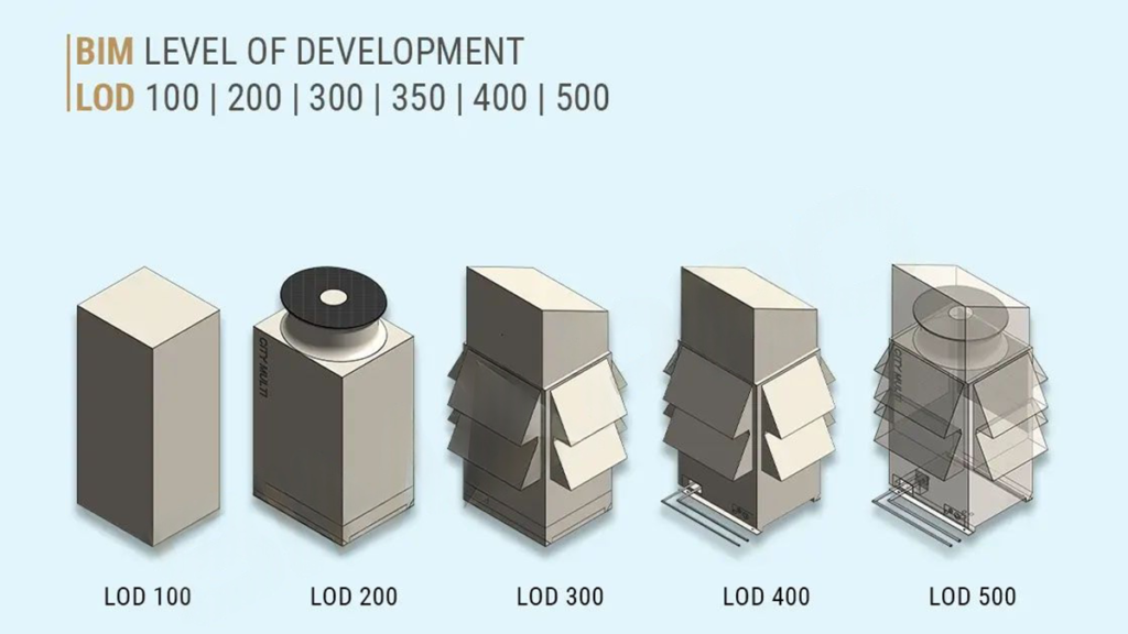
At LOD 100, model elements appear as approximate massing with basic geometric information, including overall size, height, volume, and location. Elements at this level convey design intent and spatial relationships but do not represent specific components.
LOD 100 is the starting point for feasibility studies, site analysis, early cost estimating (order-of-magnitude only), and initial programme planning. The information at this level helps project teams make go/no-go decisions on a project concept, but they should not rely on it for coordination or documentation.
Typical LOD 100 deliverables include massing studies, site models, and conceptual floor plate arrangements. The architect or owner’s representative is typically responsible for LOD 100 model content.
LOD 200 – Schematic Design
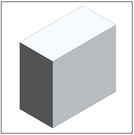
LOD 200 introduces a more geometric definition: model elements represent generic systems and components with approximate quantities, sizes, shapes, and locations. The geometry is directionally correct but not yet precise enough for coordination or documentation.
LOD 200 supports early design decisions, preliminary coordination to identify major spatial conflicts, schematic floor plans, and early cost estimating with greater reliability than LOD 100. Energy modelling and spatial feasibility checking are also valid uses at this level.
A key characteristic of LOD 200 is that it allows for flexibility. The model includes enough detail to communicate design intent while still allowing cost-effective design changes. The architect and structural engineer are typically responsible for LOD 200 content.

LOD 300 – Detailed Design and Coordination
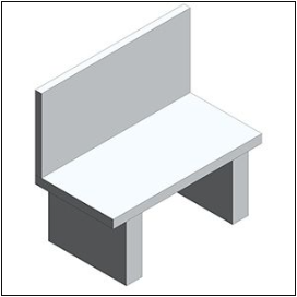
At LOD 300, project teams can confidently use the model for documentation and coordination. Elements include precise geometry, with accurate dimensions, shape, position, and orientation. Teams can use the model to produce construction documents and begin coordination between disciplines. This is where accurate construction documentation services help convert coordinated model information into drawings, schedules, and project-ready documentation.
LOD 300 supports construction documentation, permit submissions, and the early stages of clash detection. In many US projects, AIA-based contract standards require LOD 300 as the minimum level for permit and design development documentation.
But here lies the problem, as LOD 300 does not consider interfaces or clearances between various building systems. As a result, teams may detect geometric clashes between building components using LOD 300, but they may miss clearance and installation sequence clashes. This is precisely where LOD 350 steps in.
Myth: Project managers often believe that LOD 300 will suffice for all MEP coordination and clash detection needs. This is far from the truth. While LOD 300 may model the duct component, it will not consider its insulation jacket, hangers, or supports. Among the most prevalent and expensive clashes, clearance clashes demand LOD 350.
LOD 350 – Construction Documentation and Coordination
BIMForum included LOD 350 in the LOD Specification to address a long-recognized issue: project teams needed a clear way to separate model elements with accurate geometry at LOD 300 from model elements coordinated for inter-trade requirements at LOD 350.
This level is critical for system integration, where MEP BIM Services and MEP coordination services help detect issues early through Clash Detection Services, improving overall At LOD 350, model elements include all the connections, interfaces, and supports that are necessary to coordinate with adjacent building systems. For MEP elements, teams model insulation jackets, add hanger locations and drop dimensions, show sleeve penetrations through the structure, and verify maintenance access clearances.
Complex commercial, healthcare, data center, and industrial projects commonly require LOD 350 during the coordination phase. It is the level at which a BIM coordinator can run a complete and reliable clash detection report, identifying not just physical clashes but clearance violations and installation sequence conflicts.
For a detailed explanation of the clash detection process at LOD 350, see our guide: What is clash detection in BIM?
LOD 400 – Fabrication and Assembly
At LOD 400, teams develop BIM models to support manufacturing, fabrication, and assembly. All elements have precise dimensions, assembly information, connection details, and installation instructions to allow the production of building components from the model itself. Specialist contractors and fabricators typically produce LOD 400 models rather than design team members. They develop these models with fabrication and installation in mind.
There have been more applications of LOD 400 due to the increasing trend towards off-site fabrication and modularization in 2026. When fabricators produce steel joints, MEP ducting segments, and precast concrete slabs off-site, they can use LOD 400 models to achieve the exact dimensions they need.
Teams should not develop LOD 400 models too early. If they create LOD 400 models during the design phase, every design change forces them to revise fabrication-level details, which wastes modeling time.

LOD 500 – As-Built and Facility Management
LOD 500 represents the final as-built stage of the building after teams complete construction and verify the work in the field. It does not rely on assumptions. Instead, it provides a proven record of actual dimensions, coordinates, materials, and system configurations as built on site.
Building owners and facility managers value LOD 500 because it supports building operations, maintenance, and long-term facility management. The LOD 500 model acts as the basis of all the building management operations, maintenance plans, and future fit-outs.
Project teams can create an actual LOD 500 model only through field verification. They compare actual building conditions with the design model and update the model accordingly. The use of Scan to BIM services is becoming popular among firms that offer such services.
LOD 300 vs LOD 350 – The Most Important Distinction in Practice
The main misunderstanding about the BIM collaboration process comes from the differences between LOD 300 and LOD 350. Getting this wrong results in coordination models that look complete but miss the clearance conflicts that generate RFIs and site stoppages.
Reliable BIM coordination services help prevent this issue by checking model elements at the right LOD before trade packages move forward.
| Criterion | LOD 300 | LOD 350 |
|---|---|---|
| Geometry | Accurate size, shape, location, and orientation | LOD 300 + connections, interfaces, and support clearances |
| Connections modeled? | No – connections not included | Yes – brackets, hangers, penetration sleeves, insulation jackets |
| Suitable for clash detection? | Partially – major clashes identified, clearance clashes may be missed | Yes – all clash types, including clearance and installation access |
| Suitable for shop drawings? | No – insufficient detail for fabrication | Yes – shop drawings can be produced directly from the LOD 350 model |
| Who typically produces? | Architect or engineer during design development | BIM coordinator or MEP contractor during the coordination phase |
| When required? | Construction documents and permit submissions | Before trade packages are issued to subcontractors |
| Most common mistake | Issuing LOD 300 models for coordination – misses clearance clashes | Skipping LOD 350 entirely – discovered on site |
A Real-World Example of Why LOD 350 Matters
A mechanical subcontractor receives the engineer’s LOD 300 duct model and proceeds to coordination. The duct geometry is true to LOD 300 as the duct itself sits inside the ceiling cavity space. The model does not account for the insulation layer of 50 mm around the duct, the hangers, or the 150 mm clearance that should be provided above the duct.
In the federated model, the clearance requirement places the duct in opposition with a structural beam on one hand and a cable tray on the other hand. Teams cannot detect either clash at LOD 300. However, both are immediately evident at LOD 350.
The LOD 350 model surfaces both conflicts in pre-construction. These appear in the LOD 300 model – only after the erection of the steel, installation of the cable tray, and fabrication of the duct sections. It is at this stage that the cost of resolution becomes much higher than when done in the model.
What LOD Level Does Your Project Require?
LOD requirements change based on the project type, development stage, and specific needs of each model element. Below is a table showing LOD needs based on different project categories.
| Project type | Design | Permit docs | Coordination | Fabrication | Handover |
|---|---|---|---|---|---|
| Commercial high-rise | LOD 100–200 | LOD 300 | LOD 350 | LOD 400 | LOD 500 |
| Healthcare/hospital | LOD 100–200 | LOD 300 | LOD 350 | LOD 400 | LOD 500 |
| Data centre | LOD 100–200 | LOD 300 | LOD 350 | LOD 400 | LOD 500 |
| Industrial facility | LOD 100–200 | LOD 300 | LOD 350 | LOD 400 | LOD 500 |
| Mid-size commercial | LOD 100–200 | LOD 300 | LOD 300–350 | LOD 400 | LOD 400–500 |
| Residential Development | LOD 100–200 | LOD 300 | LOD 300 | LOD 400 | LOD 500 |
| Infrastructure / civil | LOD 100 | LOD 200–300 | LOD 300 | LOD 400 | LOD 500 |
Note: This table provides a general guideline. The Project BEP defines the final LOD requirements before modeling starts.
LOD and The BIM Execution Plan (BEP)
The LODs are not an isolated system. Project teams establish and implement LOD requirements in the BIM Execution Plan (BEP). The BEP defines who will model each element, at which LOD level, when they need to complete it, and in what format.
The MET identifies the LOD for every kind of building element at all milestones in a carefully designed BEP. The lack of such an agreement results in working on different LOD requirements, and this is one of the most frequent causes of BIM conflicts and budget overruns.
- Specify LOD requirements in the BEP before modelling begins, not after disputes arise
- Define LOD per element type, not per discipline. Different elements within the same model may be at different LOD levels
- Align LOD milestones with project programme and procurement dates
- Do not over-model producing LOD 400 elements during schematic design wastes modelling effort
- Reference BIMForum LOD Specification by name in contracts to avoid ambiguity
How LOD Affects Construction Cost and Project Performance
The LOD level of a model has a direct and quantifiable impact on construction cost. This is not a theoretical relationship; it operates through three specific mechanisms.
1. Clash Detection Reliability
As established above, LOD 300 misses clearance clashes that LOD 350 captures. On complex MEP-heavy projects, teams can resolve hundreds of additional conflicts during preconstruction when they coordinate at LOD 350 instead of LOD 300. Each conflict resolved in the model costs a fraction of what it costs in the field.
2. Estimating Accuracy
The LOD level of a model directly affects the reliability of quantities extracted for cost estimating. At LOD 200, models support order-of-magnitude estimates only. Once the model reaches LOD 300, teams can extract more reliable construction cost estimates. By LOD 400, the model can support procurement-level quantity takeoffs. For detailed quantity takeoffs and project cost support, explore our construction estimating services.
3. Rework Reduction
Projects that coordinate at LOD 350 consistently report lower rework rates than projects coordinated at LOD 300. The Construction Industry Institute (CII) has consistently found that rework accounts for 5–15% of total project costs on commercial and industrial projects. BIM coordination at the correct LOD level helps project teams reduce rework through a clear, documented process.
Common LOD Misconceptions Clarified
LOD vs Level of Detail – These Are Not The Same Thing
Level of Detail (LoD, sometimes also abbreviated LOD in other contexts) refers to the graphical detail of how visually complex a model element appears. Level of Development refers to information reliability, how much the project team can rely on the element for a specific purpose. A model element can be graphically detailed (high Level of Detail) but informationally unreliable (low Level of Development). The BIM Forum specification uses Level of Development exclusively.
Not All Elements In A Model Need To Be At The Same LOD
A common misunderstanding is that a BIM model has a single LOD. In practice, different elements within the same model are developed to different levels simultaneously. Structural elements may be at LOD 350 while architectural fit-out is still at LOD 200. The BEP specifies LOD per element type, not per model.
LOD 500 Is Not Always Required
LOD 500 is most valuable for complex buildings with long operational lives: hospitals, data centres, airports, and large commercial buildings. For smaller projects or projects without long-term facility management requirements, the investment in producing a verified LOD 500 as-built model may not be justified. The decision should be made explicitly in the BEP.
How Offshore BIM Teams Deliver The Right LOD, Every Time
The creation of models at the appropriate level of LOD will need more than software; it will require specialized skills, experience, and procedure. It will require someone who knows exactly what LOD 350 really entails when applied to an HVAC duct, a structural tie or plumbing connection.
Gaining such capabilities in-house takes some time since this involves hiring BIM specialists and licensing software. For many contractors and developers, the project pipeline does not justify that overhead.
At Optimar Precon, our BIM modeling services include LOD planning, model development to the specified level, and full BIM coordination services, including clash detection at LOD 350, federated model assembly, and construction documentation from coordinated models. Our offshore team delivers this at a fraction of the cost of equivalent in-house capacity, with the flexibility to scale with your project pipeline.
Visit our BIM Modeling Services if you are searching for an exclusive BIM modeling partner that knows LOD and can provide appropriate models according to all phases of the project.
Work With A BIM Team That Gets LOD Right
At Optimar Precon, we create BIM models at the right LOD for each project phase, from LOD 300 for construction documentation to LOD 350 for coordination and LOD 400 for fabrication. Our offshore BIM modeling and clash detection services help deliver coordinated models ready for construction. We support commercial, industrial, healthcare, and residential projects across global markets. To discuss the right LOD approach for your project, contact us today.
FAQs
LOD stands for Level of Development. It defines how much geometric and non-geometric information a BIM model element contains, and how reliably that information can be used for decision-making, coordination, fabrication, or facility management. LOD was formally introduced by the AIA in 2008 and is now governed by the BIM Forum LOD Specification, which is the reference standard for the US construction market.
LOD has been categorized into six different levels as follows: LOD 100 (massing for concept development); LOD 200 (schematic design with geometric approximation); LOD 300 (geometry sufficient for construction documentation and initial coordination); LOD 350 (construction documentation with all geometries and interfaces); LOD 400 (fully detailed geometry for fabrication); and LOD 500 (field verification of geometries for facility management). LOD 350 was created by BIM Forum to overcome the coordination issues that existed between LOD 300 and LOD 400.
LOD 300 includes accurate geometry, correct size, shape, and location, but does not include connections, interfaces, or support clearances between systems. LOD 350 contains all of the aforementioned elements, which makes it suitable for coordinating MEP work as well as for clash detection. The main difference between LOD 300 and LOD 350 is that clearance issues (no space left for insulation or maintenance) do not exist in LOD 300. LOD 350 is necessary for coordinating constructions with complex MEP systems.
LOD 300 provides construction documentation and coordination but does not provide fabrication-level detail. LOD 400 includes precise assemblies, connections, and installation data suitable for direct use by fabricators and specialist contractors. The key principle is not to model at LOD 400 prematurely, producing fabrication-level models during design development, which wastes significant effort if design changes occur. LOD 400 is reserved for elements that are confirmed for procurement and manufacture.
LOD 350 is required for successful clash detection, especially for clearance clashes. LOD 300 allows for major geometric clashes to be detected, but no clearance issues can be found since there are no connections or interfaces in the model. On complex MEP projects, the majority of costly on-site conflicts are clearance clashes that only become visible at LOD 350. For more information, read our article about clash detection in BIM.
An LOD 500 model is the field-verified as-built record of a completed building. It reflects what was actually constructed, including all changes made during the build. Models of LOD 500 level can be applied in facilities management, scheduled maintenance, asset management, building management system integration, and planning renovations or fit-out. In case of complicated buildings which have to work for many years, for example, hospitals, data centers, and airports, LOD 500 is a great option.
LOD requirements are set in the BIM Execution Plan (BEP) that is reached by all parties involved in the project before commencing modeling. Usually, the task of creating the BEP falls on the shoulders of either the BIM Manager or the lead designer, who will need to develop the Model Element Table that sets the required LOD for each element type at each project stage.
No. Level of Detail (sometimes also abbreviated LoD) refers to the graphical complexity or visual resolution of a model element. Level of Development refers to the reliability and completeness of information, both geometric and non-geometric, associated with an element. A model element can appear highly detailed visually (high Level of Detail) but contain no reliable data for coordination or fabrication (low Level of Development). The BIM Forum specification uses Level of Development exclusively and is the relevant standard for construction BIM.